
Static Electricity Hazards at Marine Terminals: What Every Terminal Operator Should Know
Most terminal operators reach for a bonding cable before cargo transfer begins. It seems like the right move. Connect the ship to the shore terminal, equalize the charge, prevent a spark.
ISGOTT says not to do it.
The International Safety Guide for Oil Tankers and Terminals (ISGOTT) advises against connecting a direct ship-to-shore bonding cable. A direct cable provides no benefit for static control at the connection point. Worse, connecting or disconnecting it near cargo vapors introduces the very spark hazard it is meant to prevent.
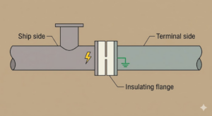
The protection mechanism ISGOTT actually requires is an insulating flange or a length of non-conducting hose at the ship-shore connection point. This deliberate electrical break separates the ship’s metal from the terminal’s metal. It controls static discharge risk without creating arcing risk at the manifold.
Static electricity is a real fire risk during cargo transfer at marine terminals. Ships and barges carry millions of gallons of flammable liquid every year. Each transfer generates electrostatic charges that can ignite vapors near loading equipment. Knowing what ISGOTT actually requires, and why, protects crews, equipment, and operations from preventable fire incidents.
How Static Electricity Builds During Marine Cargo Transfer
Static electricity forms when liquid cargo flows through pipes, hoses, and loading arms. This process is called triboelectric charging. Petroleum products, chemical solvents, and other flammable liquids generate static charges as they move through transfer equipment.
The charge does not disappear right away. It builds on metal components that are not connected to a ground point. Isolated flanges, nozzles, and manifold connections can hold these charges for several seconds. This period is called relaxation time.
The risk is highest near the fuel or chemical loading points. If a charged metal component comes close to another object at a different electrical potential, a spark can jump between them. Near flammable vapors, that spark can cause a fire.
ISGOTT recommends keeping flow rates low at the start of cargo transfer for this reason. Controlled flow gives accumulated charges more time to dissipate through a grounded path before transfer rates increase.
The Ship-Shore Interface: Where Static Risks Are Highest
The connection between a ship and a shore terminal creates specific conditions where static risks are concentrated. Loading arm flanges, manifold connections, and hose couplings are points where metal components from two different sources come together.
If these components carry different electrical potentials, a spark can occur when they make or break contact.
ISGOTT addresses this risk through electrical discontinuity rather than direct bonding. An insulating flange installed in the loading arm, or a single length of non-conducting hose in a flexible hose string, separates the ship’s metal from the terminal’s metal at the connection point.
All metal on the ship’s side of that insulating section must be electrically continuous to the ship’s hull. All metal on the terminal side must be electrically continuous to the terminal’s grounding system. This arrangement controls static discharge risk without creating the arcing hazard that a direct ship-to-shore bonding cable would introduce when connected or disconnected.
What ISGOTT Says About Grounding and Bonding
ISGOTT (International Safety Guide for Oil Tankers and Terminals) is the primary reference standard for cargo operations at marine terminals. It covers grounding and bonding requirements in detail.
ISGOTT requires verified electrical continuity within both the ship’s and the terminal’s metal systems before cargo transfer begins. Insulating flanges or non-conducting hose sections create electrical discontinuity at the ship-shore connection point to prevent arcing during hose connection and disconnection. Transfer must not begin until the insulating section is in place, the ship’s cargo system is electrically continuous to its hull, and the terminal’s piping is electrically continuous to its grounding system.
ISGOTT specifically advises against connecting a direct ship-to-shore bonding cable. This practice has no benefit for static control and creates arcing risk at the moment of connection and disconnection. Some national and local regulations still require a bonding cable, and ISGOTT provides procedures for those situations, but the cable is not the primary protection mechanism.
The OCIMF Guidelines reinforce these requirements for petroleum terminals. API RP 2003 (Protection Against Ignitions Arising Out of Static, Lightning, and Stray Currents) covers ignition prevention practices for petroleum facilities. IEC 60079-32-1 covers electrostatic hazards in explosive atmospheres and applies to equipment selection and grounding practices at marine terminals.
Non-compliance with these standards does not only create a regulatory problem. Non-compliance also creates an operational failure risk that can shut down terminal operations for days and result in serious injuries.
These standards form the technical foundation for selecting a continuous ground monitoring system.
Bonding vs. Grounding: Understanding the Difference
Bonding and grounding are related but not the same. Terminal operators regularly confuse the two terms, but the distinction matters for protection against static discharge.
Bonding connects two conductive objects so they share the same electrical potential. Connecting two sections of a terminal’s piping system together is a good example. Bonding prevents sparks when two metal parts at different potentials come into contact.
Grounding connects equipment to an earth ground point. This gives accumulated static charges a safe path to dissipate. A grounding rod driven into the earth at a terminal berth, connected to the loading arm and pump skid, is a grounding connection.
Bonding alone is not sufficient at a marine terminal. Two bonded objects can carry a high charge relative to earth. Grounding removes that charge. Together, bonding and grounding reduce the risk of static discharge during cargo transfer.
A passive bonding cable handles part of this job. What it cannot do is verify that the connection is intact during operations. A cable can become disconnected, corroded, or damaged without any visible sign to the operator. A monitored grounding system continuously verifies ground path integrity throughout cargo transfer, triggering an automatic shutdown before a static discharge incident can occur.
Hazardous Area Classification at Marine Terminals
Marine terminals handling flammable cargo are classified as hazardous locations. The National Electrical Code (NFPA 70) classifies these areas as Class I, Division 1 or Division 2 environments. Equipment rated for Class 1 Division 1, is also rated for Division 2, since the requirements for Division 1 are more stringent.
| Classification | Definition | Typical Location at a Marine Terminal |
| Class I, Division 1 | Flammable vapors exist under normal operating conditions | Area around the ship’s manifold and loading arm connection during cargo transfer |
| Class I, Division 2 | Flammable vapors may be present under abnormal conditions | Areas extending outward from the primary transfer points |
Petroleum vapors and chemical fumes in these zones have very low minimum ignition energy thresholds. The widely accepted minimum ignition guideline for fuel vapors is approximately 0.2 millijoules. A static discharge near an open loading point can carry enough energy to reach this threshold.
All electrical equipment in these zones must meet NEMA 7, 8, or 9 ratings for explosion-proof construction. NFPA 77 (Recommended Practice on Static Electricity) provides guidance on static control measures in classified areas. API RP 2003 (Protection Against Ignitions Arising Out of Static, Lightning, and Stray Currents) covers ignition prevention practices for petroleum facilities.
How Ground Monitoring Systems Work at a Marine Terminal
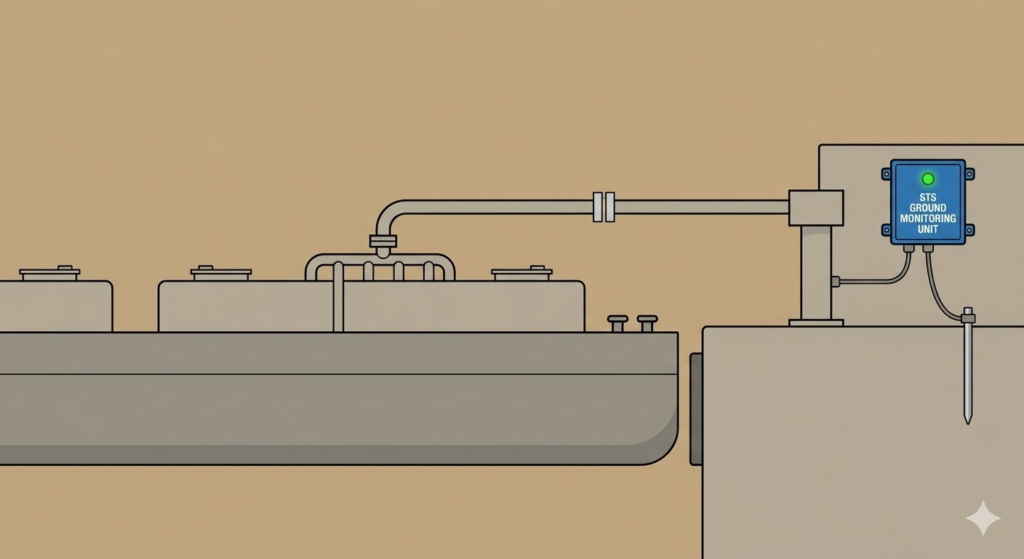
The STS 300 Series ground monitoring system continuously verifies ground path resistance throughout every cargo transfer operation. A passive cable connects equipment to earth. The STS 300 Series checks that the resistance of that path stays low enough to dissipate static charges safely throughout the entire transfer. The same equipment underpins the marine grounding systems STS supplies for barge and ship terminal operations.
The STS 300 Series monitors the full grounding circuit throughout cargo transfer. The moment resistance exceeds a safe threshold, the system signals a fault. Visual indicator lamps show status clearly to the operator. Green means the ground path is intact. Red means the connection is interrupted.
Dry contact outputs connect the monitoring system to loading pumps and valves. These contacts act as a permissive interlock. If the ground path fails, the interlock opens and stops the pumping operation automatically, without requiring the operator to notice the fault first.
Key system specifications for marine installations:
- Multipoint monitoring: The STS 300 Multipoint Grounding System monitors several connections from a single control unit, suited to terminals with multiple grounding attachment points
- Power options: 12VDC, 24VDC, 120VAC, and 240VAC to support remote berth locations where available power may vary
- Cable lengths: 10 to 100 feet to reach attachment points at various distances from the control unit
Choosing the Right Configuration and Maintaining It
Terminal size, cargo type, and berth layout each determine the correct grounding configuration.
| Terminal Type | Recommended Approach |
| Small barge operations and single-berth chemical terminals | Standard single-point monitoring system with the K78160A Grounding Clamp attached to bare metal on the ship’s hull or manifold |
| Larger vessel berths | Extended cable runs with slack factored in to account for tidal movement changing the ship’s position relative to the dock |
Salt spray, humidity, and corrosion degrade cable conductors and clamp contacts over time. Clamps must attach to bare, unpainted metal to get a reliable low-resistance connection. Painted surfaces and coated fittings add resistance to the ground path, which reduces the system’s ability to dissipate charges safely.
Regular inspection is standard practice at ISGOTT-compliant terminals. Monthly checks should confirm:
- Cable jackets are intact with no cuts, abrasion, or corrosion
- Clamp jaws are clean and make firm metal-to-metal contact
- Resistance readings are within acceptable limits
For configuration guidance by berth type and vessel size, see our marine terminal grounding systems overview.
Frequently Asked Questions About Marine Terminal Static Grounding
What is the ISGOTT grounding requirement for marine terminals?
ISGOTT requires electrical discontinuity at the ship-shore connection point, typically through an insulating flange in the loading arm or a length of non-conducting hose. The ship’s cargo piping must be electrically continuous to its hull. The terminal’s piping must be electrically continuous to its grounding system. Transfer operations must not start until these conditions are confirmed. ISGOTT advises against direct ship-to-shore bonding cables, as they provide no static control benefit and create arcing risk during connection and disconnection.
What is the difference between bonding and grounding on a ship?
Bonding connects two metal components so they share the same electrical potential. This prevents sparks when they come into contact. Grounding provides a path from the bonded system to the earth, so accumulated charges dissipate safely. Both are required for full protection during cargo transfer.
How far should a grounding cable reach at a marine berth?
Vessel size and berth layout determine the required cable length. Most marine installations use cables from 25 to 100 feet. Tidal variation should also factor into cable length selection.
Does a passive bonding cable provide the same protection as a monitored grounding system?
No. A passive cable creates a conductive path, but it provides no indication of whether that path is intact. Cables can corrode, disconnect, or break without any visible sign. A monitored system verifies ground path integrity throughout the transfer and triggers an automatic shutdown if the connection fails.
What resistance level is considered safe for a marine ground connection?
ISGOTT and API RP 2003 provide guidance on acceptable resistance levels for marine grounding circuits. The STS 300 Series monitors resistance continuously and signals a fault before levels reach unsafe thresholds.
Learn more about static grounding for marine and barge operations, or request a quote for your terminal.